Bolt Settings
- General Overview
- Tips and Tricks
- Related Tools
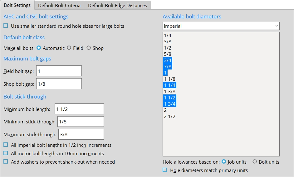
Bolt Settings
AISC and CISC bolt settings
Use smaller standard round hole sizes for lage bolts: ![]() or
or ![]() . This applies when ASD16 or LRFD16 or ASD15 or LRFD15 or CISC12 is the Connection design method; the bolt diameter (d) is 1 inch or greater; and the Hole type is set to Standard round, Short slot, Long slot, or Erection pin hole. The AISC 15th edition increased the standard hole diameter for large bolts (1 inch diameter and greater) from d +1/16 inch to d +1/8 inch (ref. Table J3.3). This setting allows you to use an AISC 15th edition Connection design method with d +1/16 inch standard hole diameter for large bolts. This setting is disabled when Available bolt diameters is set to Metric because the metric standard hole diameters did not change in the AISC 15th edition.
. This applies when ASD16 or LRFD16 or ASD15 or LRFD15 or CISC12 is the Connection design method; the bolt diameter (d) is 1 inch or greater; and the Hole type is set to Standard round, Short slot, Long slot, or Erection pin hole. The AISC 15th edition increased the standard hole diameter for large bolts (1 inch diameter and greater) from d +1/16 inch to d +1/8 inch (ref. Table J3.3). This setting allows you to use an AISC 15th edition Connection design method with d +1/16 inch standard hole diameter for large bolts. This setting is disabled when Available bolt diameters is set to Metric because the metric standard hole diameters did not change in the AISC 15th edition.
If this box is checked (
), the standard hole diameter for large bolts follows the AISC 14th edition at d +1/16 inch instead of the AISC 15th edition at d +1/8 inch.
If the box is not checked (
), the standard hole diameter for large bolts follows the AISC 15th edition at d +1/8 inch.
Note: When ASD13 or LRFD13 is the Connection design method, this setting is not available. See AISC 13th edition limit state for slip-critical bolt design.
AISC 13th edition limit state for slip-critical bolt design: This applies when ASD13 or LRFD13 is the Connection design method and the Connection Method assigned to a bolt in Project Settings > Job > Bolts, Washers, and Holes > Bolt Specifications is Slip Critical. Refer to the AISC 13th Edition, Section J3.8. Connection design uses equation J3-4 on pg 16.1-109 for slip-critical bolt design.
Design as stated in J3.8 instructs connection design to design slip-critical bolts for serviceability when a bolt fastens through a standard round hole or through a slot that is transverse to the load, but to design for strength on a bolt through an oversized hole or a slot parallel to the load.
Design all bolts with slip as a serviceability limit state instructs connection design to design all slip-critical bolts for serviceability.
Design all bolts to prevent slip at the required strength level instructs connection design to design all slip-critical bolts for strength.
Default bolt class
Make all bolts: Automatic or Field or Shop.
If Automatic is selected, the class of bolts is determined based on the following criteria: If the bolt fastens together materials that are submaterials of the same member, that bolt is a shop bolt. If the bolt fastens together materials that are submaterials of different members, that bolt is a field bolt.
If Field is selected, Field is assigned as the Bolt class to all bolts that fasten to that member. You can override this behavior: If, on the Bolt Edit window you change the Bolt class to Shop, your change is preserved through Process and Create Solids regardless of the choice made here.
If Shop is selected, Shop is assigned as the Bolt class to all bolts that fasten to that member. You can override this behavior: If, on the Bolt Edit window you change the Bolt class to Field,your change will be preserved through Process and Create Solids regardless of the choice made here.
Maximum bolt gaps
Field bolt gap: The maximum gap that you want to allow between materials with matching holes that are designated to be bolted together with field bolts.
Effect on solids creation: Create Solids automatically adds field bolts to materials with matching holes that are closer together than the maximum gap entered here. For gaps that are larger than the maximum specified here, Add Bolts gives you the option to exceed the gap.
Shop bolt gap: The maximum gap that you want to allow between materials with matching holes that are designated to be bolted together with shop bolts.
Effect on solids creation: Create Solids automatically adds shop bolts to materials with matching holes that are closer together than the maximum gap entered here. For gaps that are larger than the maximum specified here, Add Bolts gives you the option to exceed the gap.
Bolt stick-through
Minimum bolt length: The minimum length of bolt that you want to be used in this Job.
| length |
|
Effect on connection design: Bolts cannot be generated if they are shorter than the minimum length you enter here. This prevents bolts that are too short from being used in your current Job.
Note: Head thickness is not included in its calculation of bolt length because head thickness may vary among bolt manufacturers. Bolt length is calculated based on the thickness of the materials into which the bolt is inserted, the minimum amount of bolt stick through, nut thickness and washer thickness.
Minimum stick-through: The minimum distance that you want the bolt to stick through the nut after it has been fastened through the materials. Since bolt lengths come in increments of .25 inch (5 mm for metric bolts), the entry you make here should be at least .25 inch (or 5 mm) less than the Maximum bolt stick through. Otherwise, the minimum and maximum settings may be in conflict when connection design sets the bolt length.
s = stick through
![]()
Example: Suppose a 3-inch bolt has a stick through of 1/16 inch before connection design adjusts its length to comply with the minimum and maximum settings on this screen. The Minimum stick through is set to 1/8 inch and the Maximum stick through is set to 1/4 inch. Even though the current stick through is less than the minimum, the bolt length is not increased to 3 1/4 inch because the stick through would be 5/16 inch, which is greater than the maximum stick through.
Maximum stick-through: The maximum distance that you would like the bolt to stick through the nut after it has been attached through the materials. Since bolt lengths come in increments of .25 inch (5 mm for metric bolts), the entry you make here should be at least .25 inch (or 5 mm) greater than the Minimum stick through. Otherwise, the minimum and maximum settings may be in conflict when connection design sets the bolt length.
s = stick through
![]()
Example: Suppose a 3-inch bolt has a stick through of 1/16 inch before its length is adjusted to comply with the minimum and maximum settings on this screen. The Minimum stick through is set to1/8 inch and the Maximum stick through is set to 1/4 inch. Even though the current stick through is less than the minimum, the bolt length is not increased to 3 1/4 inch because the stick through would be 5/16 inch, which is greater than the maximum stick through.
All imperial bolt lengths in 1/2 inch increments: ![]() or
or ![]() .
.
If this box is checked (
If the box is not checked (
Tip: If you change this setting, you may also need to adjust the Minimum bolt length and Minimum stick through and Maximum stick through to appropriate settings.
All metric bolt lengths in 10 mm increments: ![]() or
or ![]() .
.
If this box is checked (
), connection design creates metric bolt lengths in 10 mm increments.
If the box is not checked (
Add washers to prevent shank-out when needed: ![]() or
or ![]() .
.
If this box is checked (
If the box is not checked (
Available bolt diameters
Bolt incrementation: Bolt diameters that are selected here are available to connection design when it increments bolt diameters upward in order to get a connection of sufficient strength. Incrementing of bolt diameters may be done for clip angles, shear connections, end plates, bent plates, AISC moment end plates and splice plates on beams, and for splices on columns. Bolt diameters can also be incremented on brace gusset plates and gusset clip angles when, for example, Rows and Columns are locked. Connection design does not increment bolt diameters on moment flange plates.
Selectability for modeling: Bolt diameters that are selected here are listed on every combo box ( ![]() ) for Bolt diameter throughout your current Job. See the tip below.
) for Bolt diameter throughout your current Job. See the tip below.
Both imperial & metric or Imperial or Metric: The type of bolts for which you want bolt diameters to be available for bolt incrementation (as described above).
Both imperial & metric lets the user select both Available imperial bolt sizes and Available metric bolt sizes in the same Job. When connection design attempts to increment bolts, it may select either imperial or metric sizes. Bolt tabs for clip configurations are in units that match the primary dimensioning Units.
Imperial instructs connection design to use only Available imperial bolt sizes when incrementing bolt sizes to meet loading conditions. This is commonly the selection when Imperial primary dimensioning Units are used. In setup, bolt tabs for clip angle configurations such as the Single, Bolted configurations will be in inches.
Metric instructs connection design to use only Available metric bolt sizes when incrementing bolt sizes to meet loading conditions. This is commonly the selection when Metric primary dimensioning Units are used. In setup, bolt tabs for clip angle configurations such as the Single, Bolted configurations will be in millimeters.
Tip: You can type in any metric or non-metric bolt diameters to Bolt diameter fields regardless of the selection you make here. The selection made here only sets which bolts can be selected on the combo box
( for Bolt diameter fields.)
Imperial: None or 1/4 and/or 3/8 and/or 1/2 and/or 5/8 and/or 3/4 and/or 7/8 and/or 1 and/or 1 1/8 and/or 1 1/4 and/or 1 3/8 and/or 1 1/2 and/or 1 3/4 and/or 2 and/or 2 1/2. These options are available when Imperial or Both is selected. Connection design references this list for incrementing bolts when the NM Bolt diameter (or moment Bolt diameter) is an imperial size.
When a particular bolt diameter is selected, connection design may substitute bolts of that diameter for the default or user-entered bolt size during (Process and Create Solids) if connection design determines that a larger bolt diameter is needed to build a connection that stands up to the load. This (together with settings for Imperial or Metric or Both) also sets which bolt diameters are listed on the combo box
( for Bolt Diameter fields on edit windows in Modeling.If a bolt diameter is not selected, you are still permitted to manually enter that bolt size (for example, to the default Bolt diameter for non-moment bolts).
Example: You do not select 1/2-inch bolts here, but on the Beam Edit window you enter a NM bolt diameter of 1/2. If a 1/2-inch bolt works for that connection, then connection design uses a bolt of that diameter. If a 1/2-inch bolt does not stand up to the load, connection design tries the next available larger imperial size to see if it works. If no larger bolt size is found, connection design may fail the connection or may, for example, attempt to increase the number of bolt rows to get a connection that works.
Metric: None or selected diameters from 12 mm to 40 mm. This option is only valid if Metric or Both is selected above. Connection design references this list for incrementing bolts when the NM bolt diameter (or moment Bolt diameter) is a metric size.
When a particular bolt diameter is selected, then connection design may substitute a bolt of that diameter for the default or user-entered bolt if connection design determines that a larger bolt is needed for a connection to stand up to the load. This (together with settings for Imperial or Metric or Both) also sets which bolt diameters listed on the combo box
( for Bolt Diameter fields on edit windows in Modeling.If a bolt diameter is not selected, you are still permitted to enter that bolt size manually (for example, to the default Bolt diameter for non-moment bolts).
Example: You do not select 16-mm bolts here, but on the Beam Edit window you enter a NM bolt diameter of 16. If a 16-mm bolt works for that connection, then connection design uses a bolt of that diameter. If a 16-mm bolt does not work, connection design tries the next available larger metric size to see if it works. If no larger bolt size is found, connection design may fail the connection or may, for example, attempt to increase the number of bolt rows to get a connection that works.
Hole allowances based on: Job units or Bolt units. This controls the increment that is used for sizing holes based on a bolt's diameter. The imperial increment is 1/16 inch. The metric increment is 2 mm.
Job units results in the 1/16 inch increment being used for all bolts (imperial or metric) when the primary dimension Units is Imperial. When the units are Metric, the increment of 2 mm is used for all bolts. Metric bolts that are used in a Job where the primary dimension units is Imperial will always have their holes sized less than the 2 mm increment for metric since 1/16 inch is equal to 1.5875 mm.
Bolt units results in the 1/16 inch or 2 mm increment being used based on whether the bolt is an imperial bolt or a metric bolt. If the bolts are imperial bolts, the 1/16 inch increment is used. If the bolts are metric bolts, the 2 mm increment is used. Be aware that when the primary dimension Units is Metric, conversion to mm and rounding can cause the hole size for certain imperial bolt sizes to be 1 mm smaller than you might expect given the 2 mm metric increment.
Hole diameters match primary units: ![]() or
or ![]() . This affects the hole diameters that connection design generates for bolts that have diameters in units other than the primary dimension Units.
. This affects the hole diameters that connection design generates for bolts that have diameters in units other than the primary dimension Units.
| Units = Metric (mm) | |||||
|
|
||||
If this box is checked (
If the box is not checked (
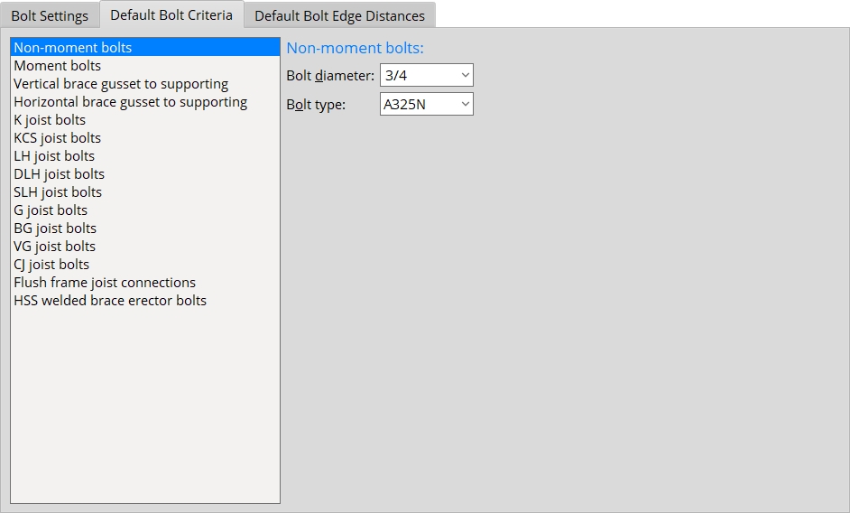
Default Bolt Criteria
Settings under this heading apply to the design of connections when ![]() Auto is checked for either moment or non-moment bolts.
Auto is checked for either moment or non-moment bolts.
Bolt diameter: The default diameter (inches or mm) of the shanks of the bolts to be used for fastening non-moment connection materials to structural members. You can either type in a diameter or select a bolt diameter from the combo box
( . The diameters that are listed come from the Available bolt diameters list on this screen.
diameter 
Note 1: The bolt diameter entered here is the default for connections and also determines which holes are identified on details when the box for Show nonstandard hole sizes on detail drawings is checked.
Note 2: When creating a non-moment, non-auto-standard connection other than a brace gusset plate, connection design determines the minimum bolt diameter from the value that is entered here or, if applicable, from the Bolt Diameter entered for structural members or from the Bolt Diameter entered for single-plate shear connections (it uses whichever value is largest). If loading conditions necessitate that connection design use a bolt diameter larger than the minimum, connection design uses one of the Available imperial bolt sizes or Available metric bolt sizes.
Note 3: Connection design calculates hole diameter from the input bolt diameter per the selected Connection design method.
Bolt type: A325N or A325SC or A325X or F1852N or F1852SC or F1852X or any other bolt listed in the Bolt Settings. This is the default bolt type for fastening non-moment connection materials to structural members. On member edit windows, the Bolt type selected here is automatically used in the design of non-moment connections when the NM bolt type to supported (beam) or NM bolt type to supporting (beam) or NM bolt type (column) or NM bolt type (horizontal brace) or NM bolt type (vertical brace) or NM bolt type (joist) is set to
. Tip: One way to get connection design to create non-moment connections with TC bolts is to select one of the F1852 bolt types. In Washer Settings, the option to Use tension control (TC) bolts is checked (
Bolt diameter: The default diameter (inches or mm) of the shanks of the bolts to be used for Bolted moment flange plates and angles, moment flange splice plates, and moment end plates. In other words, this sets the
Bolt diameter in the leaf on the Beam Edit window. Moment
diameter You can either type in a diameter or select a bolt diameter from the combo box (
Bolt type: A325N or A325SC or A325X or etc. The default bolt for moment flange plates and angles, moment flange splice plates, and moment end plates. In other words, this sets the
Bolt type in the leaf on the Beam Edit window. Bolt types on this list box (
Vertical brace gusset to supporting:
Bolt diameter: The diameter of bolts in both legs of the clip angle that fastens the vertical brace gusset to the supporting member. The bolts are made this diameter when the Bolt diameter is set to
on the Vertical Brace Edit window or in User Defined Connections. You can either type in a diameter or select a bolt diameter from the combo box ( . The diameters that are listed come from the Available bolt diameters list on this screen.
diameter 
Bolt type: A325N or A325SC or A325X or etc. This is the default bolt type for the gusset and to the supporting member. The selection made here applies when the Bolt type is set to
on the Vertical Brace Edit window or in User Defined Connections. Bolt types listed on this list box ( come from the Bolt Settings.
Horizontal brace gusset to supporting:
Bolt diameter: The diameter of bolts in both legs of the clip angle that fastens the horizontal brace gusset to the supporting member. This diameter is applied when the Bolt diameter is set to
on the Horizontal Brace Edit window or in User Defined Connections. You can either type in a diameter or select a bolt diameter from the combo box ( . The diameters that are listed come from the Available bolt diameters list on this screen.
diameter
Bolt type: A325N or A325SC or A325X or etc. This is the default bolt type for fastening the clip angle to both the gusset and to the supporting member. The selection made here applies when the Bolt type is set to
on the Horizontal Brace Edit window or in User Defined Connections. Bolt types on this list box ( come from the Bolt Settings.
K or KCS or LH or DLH or SLH or G or BG or VG or CJ joist bolts.
Bolt diameter: The diameter (inches or mm) of bolts per joist type (K or KCS or LH or DLH or SLH or G or BG or VG or CJ). You can either type in a diameter or select a bolt diameter from the combo box
( . The diameters that are listed come from the Available bolt diameters list on this screen.
diameter This diameter applies when, on the Joist Edit window, a K or KCS or LH or DLH or SLH or G or BG or VG or CJ joist has been entered as the Section size and the box for
is checked for the joist end's NM bolt diameter. It and Bolt type (below) apply to the design of connections for a joist bolted to a beam flange (bearing connection) an auto cap plate supporting a joist (bearing connection), and of various types of joist top chord seats (seated connection). Example: CJ joists become available when the Joist manufacturer is Vulcraft. When their connection type is a flush framed joist connection, they -- as well as other types of joists with flushed framed joist connections -- will be assigned the auto bolt diameter that is specified, on this screen, under Flush framed joist connections. When a CJ joist has a bearing connection or seated connection, the auto bolt diameter used in that connection will be the Bolt diameter that is specified here, under CJ joist bolts.
Bolt type: A325N or A325SC or A325X or etc. This is the default bolt type to be used for K or KCS or LH or LH or DLH or SLH or G or BG or VG joists. Bolt types on this list box
( come from the Bolt Settings.Effect on connection design: The bolt type selected here applies when, on the Joist Edit window, a K or KCS or LH or DLH or SLH or G or BG or VG or CJ joist has been entered as the joist's Section size and
is checked for the joist end's NM bolt type.
Flush framed joist connections:
Bolt diameter: The diameter (inches or mm) of bolts to be used when a joist Input connection type is Flush framed shear or Flush framed clip angle and when the box for
is checked for the joist end's NM bolt diameter.
diameter Example: If you enter, on this screen, one bolt diameter for K joist bolts and a different bolt diameter for Flush framed joist connections, the actual auto bolt diameter that is applied by connection design will depend on the connection type. If the end connection is a bearing connection or seated connection, the auto bolt diameter will be the bolt diameter for K joist bolts. If the end connection is a flush framed connection, the auto bolt diameter will be the choice made here, under Flush framed joist connections.
Bolt type: A325N or A325SC or A325X or etc. The default type to be applied when a joist Input connection type is Flush framed shear or Flush framed clip and the box for
is checked for the joist end's NM bolt type.
HSS welded brace erector bolts:
Bolt diameter: The diameter (inches or mm) of erection bolts that connection design will create when an HSS vertical brace Pipe/tube end-fitting or HSS horizontal brace Pipe/tube end fitting is set to Welded and the NM bolt diameter (vertical brace) or NM bolt diameter (horizontal brace) is set to
.
| diameter |
|
Bolt type: A307 or etc. The choice made here is applied, by connection design, when an HSS vertical brace Pipe/tube end-fitting or HSS horizontal brace Pipe/tube end fitting is set to Welded and the NM bolt type (vertical brace) or NM bolt type (horizontal brace) is set to
. The default bolt type that is set here for HSS welded brace erector bolts is A307.
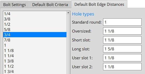
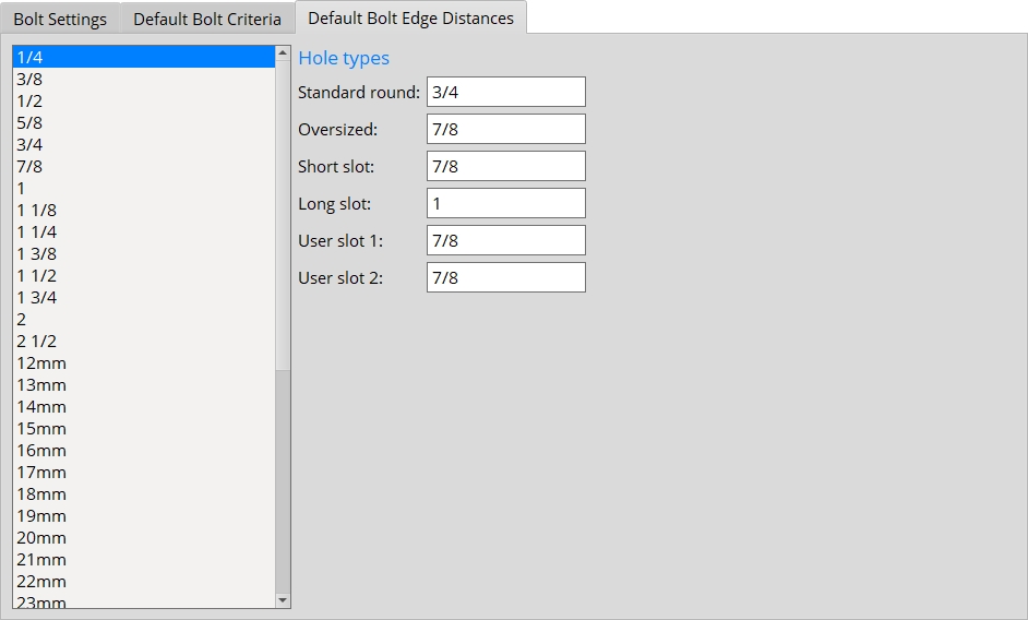
Default Bolt Edge Distances
Bolt diameter: 1/4 or 3/8 or 1/2 or 10 or 11 or 12 or any other selected bolt diameter. When you select a bolt diameter, you get entry fields for setting the minimum edge distance per hole type.
|
| User slot #1 and User slot #2 are slots that are defined by users (or by default) in Project Settings. |


|
|
OK (or the Enter key) closes this screen and applies the settings.
Cancel (or the Esc key) closes this screen without saving any changes.
Reset undoes all changes made to this screen since you first opened it. The screen remains open.
- If you have made changes to this screen after having added members to the 3D model, you should interactively mark for processing (or Process Selected) all members in your current Job, then Process and Create Solids in order to ensure design consistency throughout the Job.
- Red or yellow exclamation point icons
 or
or 
- Bolt Specifications (sets available bolts)
- Connection design (settings on this screen are applied during)

